Limitations on the Size of Flex Circuit Boards
Size of Flex Circuit Boards
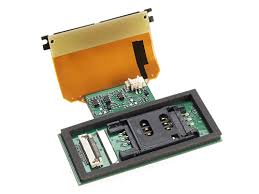
A flex circuit board is a single or multi-layer PCB that can be bent and shaped to fit the product it will be installed in. These boards are often used in mobile devices, tablets, computers, and printers. They are also found in a variety of medical equipment, industrial control, and aerospace/military products. They are a great choice when designing for a specific product because they allow the device to be placed in any position. The flex circuit is flexible and durable, making it suitable for harsh environments.
While it is possible to make a flex circuit thicker than the minimum thickness recommended, there are some limits that need to be considered. For example, a flex circuit must be able to bend without damage to the copper traces and/or other components. To avoid damage, the copper traces should be positioned away from hard right angle bends and 45-degree hard corners. In addition, the flex circuit should not be positioned near plated through holes or buried vias. These are metalized through holes that connect the conductive layers of the circuit. They can increase the stress on the flex circuit during bending. If the flex circuit is thin enough, it will not be able to resist the stress and may break.
The metallurgy of the copper foil used to create the traces on a flex circuit board needs to be taken into account as well. If the flex circuit is being designed to be a component in a rugged application that will be subjected to repeated bending, it is best to use high-grade rolling annealed (RA) copper. This type of copper is able to stretch longer before fatigue cracking starts and is springier in the z-deflection direction. The RA process adds to the cost but is worthwhile when considering a robust design for a flex circuit.
Limitations on the Size of Flex Circuit Boards
To ensure that the flex circuit is able to withstand a variety of different stresses, the manufacturer should consider adding an epoxy resin over the surface of the board. This layer of epoxy will provide additional strength and stability to the flex circuit and prevent any corrosion or other problems from occurring. This is especially important if the flex circuit will be subjected to harsh environmental conditions, such as heat, moisture, chemicals, and shock.
It is possible to add a layer of solder mask to the flex circuit to protect it from contamination during assembly and testing. However, the cost of this will increase the price of the flex circuit. The flex circuit will also need to be tested by an electrical test house to make sure that it functions as intended and is not defective.
The final decision as to the size of a flex circuit depends on the design specifications and the final product. While there are some restrictions, it is possible to have a very complex flex circuit board if the designer follows the proper guidelines. Trace widths and spacing requirements, trace to pad spacings, and pad sizes are typically the same as those for rigid circuit boards but will vary in other areas due to the flexible nature of the polyimide materials used, the flex material dimensional tolerances, and the plating process.


Recent Comments